Thickness variation, poor adhesion, skip plating, solderability failures, and contaminated rinse water usually begin with small process changes that go unrecorded. By the end, you will be able to connect each stage of a PCB finishing line to its control variables, verification method, and corrective action.
Key takeaways
- Keep each process stage from carrying chemistry into the next tank.
- Use anode placement, rack design, and agitation to control current distribution.
- Separate rinsing and maintain filtration to limit cross-contamination.
- Prove consistency with thickness maps, bath analysis, and adhesion tests.
How Each Process Stage Protects the Next One
A PCB plating line stays consistent when every stage leaves a controlled surface for the next one. Cleaning must remove oils and residues without carrying alkaline chemistry into micro-etching; micro-etching must refresh copper without reducing feature dimensions or weakening narrow traces.
1. Verify cleaning concentration, temperature, spray pressure and dwell time. Under-cleaning leaves organic films that cause skips and poor adhesion; over-treatment wastes process margin. Measure the rinse condition after cleaning, not just the tank chemistry.
2. Control micro-etching by copper removal rate, temperature, concentration and exposure time. Inspect panels for uniform wetting and surface appearance, then prevent drag-in with adequate rinsing.
3. Treat activation process control as a chemistry check, not a visual step. Confirm catalyst coverage, bath age and replenishment, because incomplete activation creates bare areas while excessive treatment changes the deposit response.
4. Hold copper, tin, or nickel-gold baths within their qualified metal, acid, pH, additive, temperature and agitation ranges. Analyse major constituents and use a Hull cell, cyclic voltammetric stripping, or a calibrated test panel to verify additive balance.
5. Rinse after every treatment with sufficient overflow and spray coverage. Counter-current rinsing saves water, but stagnant zones, rack drag-out, or rising conductivity can return acid, metal ions, and treatment chemistry to the next tank.
6. Dry with uniform air flow and controlled temperature so water marks, ionic residue, and trapped moisture do not remain in holes or under features. Segregate incompatible concentrated wastes before treatment rather than sending them into one unstable stream.
How Current Distribution and Equipment Geometry Control Thickness
A rectifier set to 100 A does not guarantee uniform copper thickness. The result depends on local current density: board edges and exposed copper features draw more current than recessed areas, while small vias and high-aspect-ratio holes may receive too little.
Plants correct that imbalance through a qualified geometry recipe, not improvised adjustments. The recipe fixes anode-to-cathode spacing, panel orientation, shielding, thieves, conforming anodes, and solution movement for each panel size and feature pattern. Changing rack position or panel spacing can shift the deposit profile even when amperage and plating time remain unchanged.
Electrical contact is part of the circuit, not a mounting detail. Inspect rack contacts and bus-bar contact points for oxide, plating buildup, looseness, and polarity errors; rising contact resistance reduces the current reaching one panel. Compare the rectifier indication with an independently calibrated meter at scheduled intervals.
Anodes must present a clean, stable area across the panel. Incorrect anode area, uneven spacing, damaged or missing anode bags, poor basket contact, and accumulated anode slime create hot spots, particles, or both. Clean sludge before it enters circulation, inspect bags for tears, and keep anode condition in the approved process recipe.
Arrange panels with consistent spacing and orientation throughout the flight bar. Controlled agitation then refreshes solution at holes and recessed features without creating excessive gas pits or foam. Validate the arrangement with thickness coupons or mapped measurements; a visually sound board can still hide thin hole walls or overbuilt edges.
How Rinsing, Filtration, and Wastewater Handling Prevent Cross-Contamination
An overflowing final rinse can return process chemistry to the next tank and destabilise a previously stable finish. Use counterflow rinsing so clean water enters the last rinse and flows toward the process tank; set overflow and spray coverage to prevent stagnant zones, then use conductivity checks to detect contamination before boards carry it onward.
Reduce drag-out at the source. Drain racks above the process tank and route concentrated solution to drag-out recovery instead of the rinse. Use a dedicated transfer path with verified connection points, add secondary containment, label every connection, and interlock additions that could create an incompatible reaction.
Filtration removes particles from the bath, but only when actual flow reaches the work: verify the filter is not bypassing or cavitating, and replace loaded or contaminated media.
Segregate wastewater according to chemistry:
- Acidic and alkaline rinses: keep separate until neutralisation is controlled.
- Metal-bearing rinses: route to treatment designed for metal precipitation.
- Cyanide- or complexant-containing wastes: isolate until their specific treatment step.
Indiscriminate mixing can reduce metal-removal efficiency, create hazardous reactions, and make compliance samples misrepresent the discharge. Local exhaust must also match the tank chemistry, because mist and spills can carry contamination into nearby rinse sections.
Which Measurements Prove That the Deposit Is Consistent
A consistent deposit is proved by matching bath data, electrical data, and measured deposit results. Record pH, bath temperature, metal concentration, additive balance, rectifier output, plating time, and solution turnover against the bath-control schedule.
Place the temperature sensor in well-mixed solution that reaches the panels, not beside a heater or tank wall; a convenient reading can hide local overheating.
- Check pH and bath temperature at the start of each shift and after replenishment; log continuous temperature alarms where the controller supports them.
- Analyse metal concentration and major constituents at the schedule set by the chemistry supplier, then repeat after an abnormal drag-in event, prolonged shutdown, or major addition.
- Use cyclic voltammetric stripping, a Hull cell, or a calibrated test panel to verify copper-plating additives; copper and sulfuric-acid titrations alone cannot prove suppressor, accelerator, leveler, or chloride balance.
- Measure thickness by X-ray fluorescence at the panel centre, corners, edges, pads, and representative through-holes or blind vias. Microsection production coupons at the qualification frequency and after process changes.
| Measurement | Sample location | Confirmation |
|---|---|---|
| Thickness map | Panel corners, centre, features | Uniform XRF readings and cross-section results |
| Adhesion | Production coupon or panel | No lifting after approved tape, thermal-stress, or pull testing |
| ENIG quality | Nickel and gold layers separately | Nickel thickness and phosphorus condition meet specification; gold is not used to hide nickel corrosion |
| Solderability | Representative finished pads | Wetting and solder-joint testing pass; visual gold colour alone proves nothing |
How to Specify a Line That Repeats the Process, Not Just the Motion
A line repeats the process only when it controls both motion and bath condition. Equipment repeatability means the same recipe produces the same rack position, dwell time, current, agitation, temperature at the work, and transfer sequence every cycle.
Chemical-process control asks whether the bath still has the composition and activity needed to produce the specified deposit.
1. Ask for repeatability data, not a statement that the line is automatic. Check recorded current and voltage, rectifier accuracy, flight-bar speed, tank-to-tank timing, agitation rate, dosing resolution, and temperature readings from solution reaching the boards rather than from a heater or tank wall.
2. Define chemical checks beside each equipment value. Copper metal and sulfuric acid assays do not prove additive concentration; use titration or instrumental analysis for major constituents, then use cyclic voltammetric stripping, a Hull cell, or calibrated test panels to assess suppressor, accelerator, leveler, and chloride balance.
3. Specify acceptance limits for the finished deposit. Require X-ray fluorescence thickness readings at named board locations, plus adhesion, solderability, or porosity tests where the finish demands them. For ENIG, separate nickel thickness and condition from the thin immersion-gold layer, and record pH, temperature, gold concentration, bath age, and immersion time.
Associated Surface Innovators can support a useful comparison by documenting sensor locations, dosing points, sampling ports, and data records in the line specification rather than leaving them to commissioning.
Upgrade the weaker control loop first: a precise machine cannot rescue an exhausted bath, while a well-controlled bath cannot overcome inconsistent current or timing.
Related products
 | PCB Plants We manufacture highly reliable and robust PCB Plating Plants designed to support efficient electroplating processes in the printed circuit board... View product → |
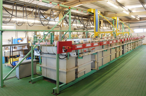 | Electroplating Plants We are engaged in fabricating highly efficient Electroplating Plant Manufacturer, which is available in different operating options such as... View product → |
Frequently asked questions
How does each PCB plating stage protect the next one?
Cleaning removes oils and residues, while controlled micro-etching refreshes copper without damaging traces or reducing feature dimensions. Each rinse must remove carryover before the panel enters the next chemistry.
How do current distribution and equipment geometry control plating thickness?
Anode placement, rack contacts, panel spacing, shielding, agitation, and rectifier control determine where current concentrates. Balance these factors to reduce heavy deposits on edges and thin deposits in recessed areas.
How do rinsing, filtration, and wastewater handling prevent cross-contamination?
Use staged rinsing, adequate overflow, clean water flow, tank filtration, and separate waste streams to remove drag-out before it reaches another process bath.
Which measurements prove that a PCB deposit is consistent?
Compare thickness maps across defined panel locations, then verify bath chemistry, rectifier output, temperature, pH, adhesion, solderability, and surface appearance against process limits.
Keywords